Unfortunately, the selection of high voltage electrolytic capacitors today is both
smaller and different from the past, so chances are you won't find an exact replacement
for your original equipment electrolytics. For low voltage applications, like cathode
bypass capacitors, most vintage types have an axial configuration, which is less common
today but still available. The more modern radial configuration can also be used if
their leads are long enough and they don't violate your notion of aesthetics.
More problematic are the high voltage power supply capacitors, usually multi-sectioned aluminum can types mounted on the chassis top plate. To repair these, you have perhaps four options:
Electrolytics do not suffer idleness well. They can cause big trouble when idle for long periods, needing periodic charging to stay "formed" and maintain the oxide layer that insulates the conducting plates. Sometimes they can be "reformed" by a slowly rising return to working voltage (see below). Even with regular use, electrolytics fail with age by drying out or leaking electrolyte following internal corrosion. If the electrolytic bulges, shows obvious loss of electrolyte, or simply can't be reformed you must replace it.
Note there are two types of leakage; physical and electrical. Since the electrolyte is a liquid or paste, when an electrolytic catastrophically fails it usually oozes some corrosive goop: physical leakage. Unlike an ideal capacitor, electrolytics slightly conduct when there's voltage across the plates: electrical leakage. Other than being a deviation from ideal behavior, the small leakage in a new electrolytic causes no major problems; as the electrolytic ages, the leakage increases. The leakage generates heat, which ages the electrolytic and increases leakage, causing more heat, and so forth. With enough leakage, the electrolyte boils, and the steam bursts the safety plug of the container causing physical leakage and signaling the demise of the capacitor.
Note also that there are other forms of terminal failure, including complete loss of capacitance (open) or bridging of the conducting plates (short). While you may be able to reform your 30 to 50 year old original electrolytics, they may not perform as well as when new. There may be a partial loss of capacitance, or there may be excessive leakage (the caps get really warm), or both. Unless you want to preserve the original condition of your amplifier, preemptive "recapping" may be the best course to restore the equipment to functionally original condition.
Current-Limited Method (from Angela Instruments): Here's a link to Angela instruments's instructions for reforming old electrolytics out of their chassis using an external power supply. This method uses a large series resistor and a high-voltage power supply to reform capacitors that are NOS (new-old stock) or capacitors removed from the equipment's chassis.
Voltage-Limited Method 1: The voltage-limited methods use a handy device called the variable autotransformer (a.k.a. Variac, General Radio's brand name). Using a high-voltage external power supply, each capacitor is slowly brought up to working voltage by slowly raising the line voltage to the power supply. This can also be done with a variable DC supply with a range from about 50V to 500V, but variacs are cheaper and more common. A resistor can be placed in series to monitor the current, but watching the voltage also can reveal reforming progress; at each variac setting, the voltage will slowly rise until reforming at that voltage is complete.
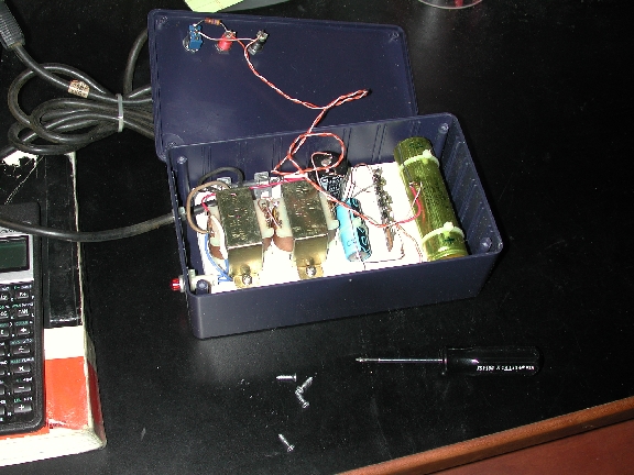
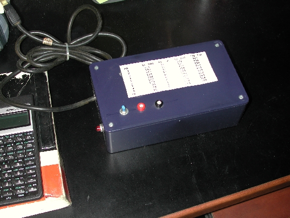
It's easy to make a supply for this purpose from junk-box parts; the circuit is a pair of 500mA 24V transformers connected secondary to secondary, followed by a voltage tripling circuit. Total cost was about $10 (really), including the box from the local Radio Shack. Being a voltage tripler, regulation is weak and the voltage drops a lot as current increases. I've exploited this characteristic to give a rough estimate of the current drain, as shown in the chart on top of the supply. (The values were measured using a rheostat and my DMM - a supply using a different collection of parts would have similar behavior, but would measure differently). Typically I would connect my supply across the electrolytics to be reformed, along with my DMM set to its highest voltage setting. I plug my supply into the variac (turned off, set to zero), turn the variac on and slowly increase to the 30 volt setting. If the voltage reading on the DMM does not rise, or rises to less than 95 volts, there's likely a short. If the voltage rises, the voltage indicates the current drawn by the supply. As the capacitor starts to reform, the leakage current will decrease and the voltage will continue to rise. Once the leakage has decreased to an acceptable level, I go stepwise upward with the variac setting until the operating voltage for the capacitor is reached.
In the equipment's chassis, often capacitors of different voltage ratings are connected by voltage-dropping resistors, and the equipment uses the current demands of the circuit to keep voltages in operating range. You could disconnect each capacitor from the circuit and reform individually, or perhaps follow method 2.
Voltage-Limited Method 2: Using a two stage method, we can use the load of the circuit to keep the voltages in all the circuit's power supply capacitors within operating range. This is the method that I usually use, and can be carried out by using the equipment's own power supply. Look at the circuit and note the lowest voltage rating of all the capacitors that connect to the high voltage (B+) supply. Remove the tubes from the chassis and, using a variac, reform the power supply capacitors to this lowest voltage. Now put the tubes in the chassis and raise the highest-voltage-operating capacitor to this minimum voltage. This typically gives about 60% of the B+ and enough of the filament voltage to provide a load. Raise the line voltage slowly (using your variac) to reform the resistor-connected power supply capacitors each to its own working voltage (or slightly above).
This method has some more risk compared to reforming out of the chassis - you'll need to watch the total current draw and raise the voltage more slowly, since you have less information about the condition of the individual capacitors. Remember that it's quite likely that all of the connected capacitors except one will reform, but that one bad section will draw lots of current. You cannot assume that, if the acceptable leakage for one electrolytic is 1 mA, then it's ok for 4 electrolytics connected together to have leakage of about 4 mA - your group of 4 electrolytics must have a combined leakage less than that allowed for a single electrolytic otherwise you've allowed the possibility of 3 of good quality and 1 clunker.
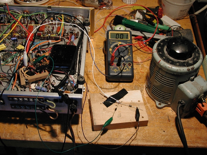 If the equipment has a vacuum tube rectifier, you must jumper it with some
silicon diodes for this method to work. It's really easy though - remove the
rectifier and use some clip leads and a couple of 1N4007s as shown in this picture.
WARNING - this method obviously leaves wires exposed while you work. These
wires are potentially at HIGH VOLTAGES which can kill.
For example, if you rest your right hand on the variac (ground) and touch the
exposed clip leads, that will form a circuit from one arm, through your chest,
and down through the other arm - potentially causing cardiac arrest. To me, this
seems no more hazardous than working around live tube equipment with the covers
off, though extreme caution is warranted in both cases. Proceed at your own risk!
If the equipment has a vacuum tube rectifier, you must jumper it with some
silicon diodes for this method to work. It's really easy though - remove the
rectifier and use some clip leads and a couple of 1N4007s as shown in this picture.
WARNING - this method obviously leaves wires exposed while you work. These
wires are potentially at HIGH VOLTAGES which can kill.
For example, if you rest your right hand on the variac (ground) and touch the
exposed clip leads, that will form a circuit from one arm, through your chest,
and down through the other arm - potentially causing cardiac arrest. To me, this
seems no more hazardous than working around live tube equipment with the covers
off, though extreme caution is warranted in both cases. Proceed at your own risk!
Some final cautions:
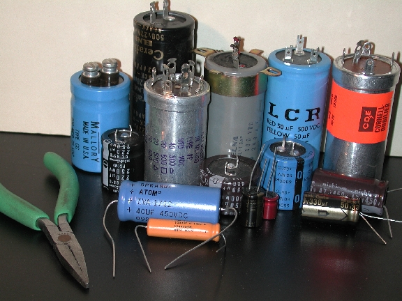
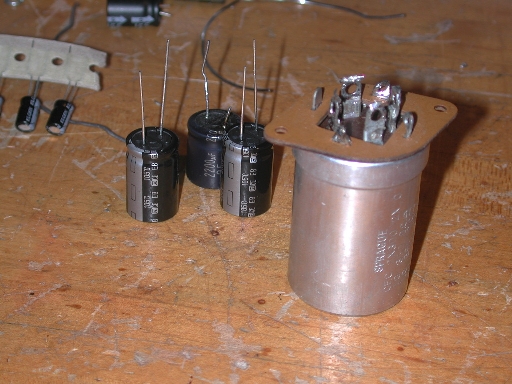
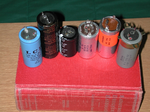 From left to right, we have a LCR computer capacitor, an Elna Cerafine
computer type (unfortunately no longer in production), a Panasonic TSHA snap-mount
capacitor, a new-production Aero-M twistlock, a NOS Mallory twistlock,
and a good-but-used Elna removed from equipment.
From left to right, we have a LCR computer capacitor, an Elna Cerafine
computer type (unfortunately no longer in production), a Panasonic TSHA snap-mount
capacitor, a new-production Aero-M twistlock, a NOS Mallory twistlock,
and a good-but-used Elna removed from equipment.
Twist-Locks can be purchased NOS (new old-stock) through regular retail channels and at swap meets, from old electronic store stocks, and so forth. Most of these types have multiple sections (i.e. more than one capacitor in the can) and were built with many different combinations of sections in both capacitance and voltage rating. Last I heard, Aero M/Mallory had discontinued the production of replacement twistlock electrolytics, but a recent newsgroup post claimed that production would be resumed if there were demand. Antique Electronic Supply presently has a limited stock. Good used twistlocks can sometimes be removed from old equipment or found at electronics swap meets.
Used or NOS replacements should be reformed before installation. Since the variety of good used or NOS types becomes more and more limited with time, you may have to settle for fewer sections than in the original capacitors. This needn't be a problem if you can hide the remaining sections in the equipment chassis. You can also accept replacements with higher capacitance than the original, by as much as 60% to 80% and perhaps more depending on the location in the circuit. Do not, however, use a replacement with a lower voltage rating than the original equipment (higher rating is ok, even desirable). Sections can also be paralleled to give higher capacitances; for instance, if you needed a 40/20/20/25uF@450/350/350/25V, and you found a 20/20/20/20uF@500/500/500/500V replacement capacitor, you'd wire two of the 20uF sections in parallel to give 40uF@500V, and use the two remaining 20uF@500V sections at 350V, then put a 25uF/25V capacitor in the chassis somewhere.
Replacement is straightforward, but make good notes about the wire locations before any unsoldering. Also pay attention to the locations of the ground lugs so that, when the new cap is installed, all the ground wires will reach their lugs.
Computer Caps vary in their height and diameter; if they can fit on your chassis, you may choose from many physical sizes for your project. Both screw terminal and lug (Faston type) connectors are used. Although many diameters and voltage ratings are available, we will focus on high-voltage computer caps with 1.3125" diameter and multiple sections. This diameter matches the usual diameter of twist-locks discussed above, and thus can be used for replacement without major equipment modification.
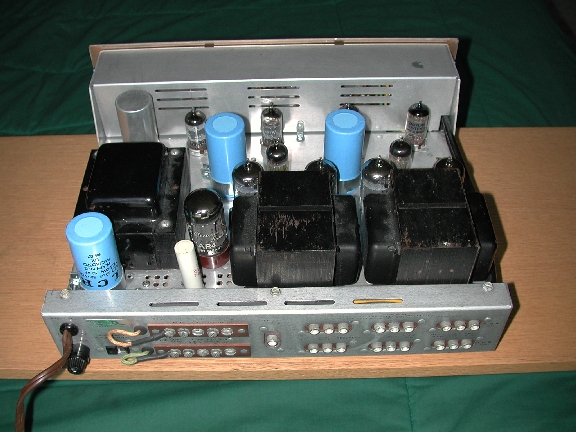 The blue plastic jacketed electrolytics made by LCR are discontinued (some
stock is still out there), but similar capacitors continue to be produced by
JJ Electronics in Slovakia. The black jacketed and audiophile-targeted Elna
Cerafines have been discontinued, although audiophile targeted Black Gates
can be purchased for outrageous prices, but I can't afford to own examples
of those. For JJs,
Triode Electronics,
Angela Instruments,
Parts Express. For Black
Gates, Handmade Electronics, Angela Instruments, other parts suppliers
on my home page. An example of my Scott 299C recapped with LCRs is shown
on the right.
The blue plastic jacketed electrolytics made by LCR are discontinued (some
stock is still out there), but similar capacitors continue to be produced by
JJ Electronics in Slovakia. The black jacketed and audiophile-targeted Elna
Cerafines have been discontinued, although audiophile targeted Black Gates
can be purchased for outrageous prices, but I can't afford to own examples
of those. For JJs,
Triode Electronics,
Angela Instruments,
Parts Express. For Black
Gates, Handmade Electronics, Angela Instruments, other parts suppliers
on my home page. An example of my Scott 299C recapped with LCRs is shown
on the right.
Mounting these caps requires a clamp screwed to the chassis, and you'll usually have to add some holes for the clamp attachment, and perhaps enlarge the clearance hole for the connection lugs. Clamps can be found at Mouser Electronics for about 50c. Typically, there are fewer sections compared to the original twist-locks, so some of the sections must be moved into the chassis.
Snap Mount Caps usually mount on a PCB (printed circuit board). The pins snap in to holes in the PCB and stay there well enough to be wave soldered in place. It's easy to solder directly to the pins ... and some snap mounts have the right diameter (35mm) to replace twist-locks using the same clamps used with the computer caps above. Unfortunately, with only one section, you still have to hide the remaining sections in the chassis, although they provide the opportunity to fill some of the chassis real estate with high-quality capacitance rather than with a dead capacitor. Check out the Panasonic TSHA or TSHB (from Digikey Electronics) or Nichicon NT (Michael Percy, but likely other vendors too).
 Because of the compact size of modern capacitors, usually you can find enough space
within your equipment's chassis to locate replacement capacitors. If you can resolve
the mechanical issues, modern styles of capacitors also have much higher performance
than vintage types, thus you may enjoy a sonic benefit by only employing modern
styles of caps for your replacement, rebuild or repair.
Mechanical issues include
Because of the compact size of modern capacitors, usually you can find enough space
within your equipment's chassis to locate replacement capacitors. If you can resolve
the mechanical issues, modern styles of capacitors also have much higher performance
than vintage types, thus you may enjoy a sonic benefit by only employing modern
styles of caps for your replacement, rebuild or repair.
Mechanical issues include
When you select capacitors for under-chassis mounting, be aware of the quality of the capacitor you plan to use. I know from personal experience that cheap generic surplus electrolytics will burst if subjected to high ripple current. Especially for the capacitor electrically closest to the rectifier, choose a high quality new capacitor specifically intended for high ripple currents, such as the Panasonic EB (available from Digikey Electronics).
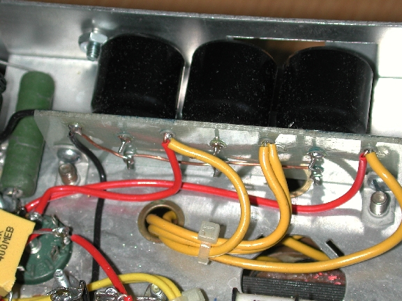
Above are 3 47uF/400V Panasonic TSHA mounted on a piece of glass fiber board (FR4) using grommets. Grommets and staking tool are manufactured by Keystone and available from Mouser Electronics. You can also etch circuit boards for this purpose; Sheldon Stokes of SDS Labs built some high quality replacement boards for the Harmon-Kardon Citation II and the Dynaco ST-70. Seems a shame not to use the chassis space occupied by the twistlock caps, but Sheldon's boards are a very neat solution. Some of Sheldon's boards are also sold by Triode Electronics.
SERIES-CONNECTED CAPACITORS: Insufficient voltage ratings can be a problem, and series-connection may be the only way to obtain electrolytics with a high enough voltage rating. I know of only a very few modern-style electrolytics with voltage ratings above 450V, including LCRs (500v) and Sprague Atoms (600V). Series-connection requires addition of so-called "bleeder" or voltage balancing resistors, one across each capacitor, conducting a current that keeps the voltage across the series capacitors balanced. Some of this is covered in the manufacturer's application notes; sources here are the Nichicon and Rifa application notes in particular.
 Even brand-new high quality electrolytic capacitors conduct to some degree. This
leakage current depends on the quality of the electrolyte, temperature and condition of the
capacitor, and can be represented by a resistance in parallel with the capacitor.
In the figure, series-connected capacitors
C1 and C2 have some leakage resistance RL1 and RL2. Because of
the wide tolerances of electrolytics, this leakage current varies from sample
to sample, and by Ohm's law, effects the voltage balance between electrolytic
capacitors connected in series. Note that we consider only brand new, identical
capacitors connected in series - no mixing of ratings, types or brands, please.
Even brand-new high quality electrolytic capacitors conduct to some degree. This
leakage current depends on the quality of the electrolyte, temperature and condition of the
capacitor, and can be represented by a resistance in parallel with the capacitor.
In the figure, series-connected capacitors
C1 and C2 have some leakage resistance RL1 and RL2. Because of
the wide tolerances of electrolytics, this leakage current varies from sample
to sample, and by Ohm's law, effects the voltage balance between electrolytic
capacitors connected in series. Note that we consider only brand new, identical
capacitors connected in series - no mixing of ratings, types or brands, please.
Balance resistors RB1 and RB2 keep the voltage balance between the series capacitors within tolerance by including another larger current in parallel with the leakage current. The balancing current is chosen large enough to overwhelm any leakage imbalance and thereby to guarantee safe operation. To calculate the value of the balancing resistors, first determine the approximate maximum leakage of the series-connected capacitors. The leakage current in uA ranges from 1/5 sqrt(CV) to 1/2 sqrt(CV) according to Nichicon, with C in uF, V in volts and current in uA. You can also get leakage specifications from your capacitor's data sheet. One common rule-of-thumb for the balancing current is 10x the leakage current - thus for two 100uF/350V capacitors connected in series to form a 50uF capacitor, maximum leakage of 1/2 sqrt(100*350) = 94uA, times 10 is about 1 mA. Let's say we want our applied voltage to be 650V, then RB1 and RB2 = 325K ohms. Power dissipation of I*V = 0.325W, so a minimum 1W resistor would give an adequate safety margin. Be sure to check the voltage rating of any balancing resistors too.
You'd think that two 350V electrolytics connected in series would have a voltage rating of 700V, but the loose tolerances of electrolytics again interferes. As pointed out in the Evox Rifa electrolytic capacitor application note, series capacitors act as a capacitive voltage divider, and N electrolytics connected in series with a capacitance tolerance range of Cmin to Cmax have a maximum divided voltage (at the junction of the two capacitors) Vdiv = (Vapplied * Cmax) / (Cmax + (N - 1) * Cmin). Ok, so in our example, with a +/- 20% capacitance tolerance, Cmax = 1.2*100 and Cmin = 0.8*100, with Vdiv = (650*120)/(120 + (2-1)*80) = 390V. This exceeds the voltage rating of the electrolytics by 40 vots; with some algebra we can see that 350+350 gives a 583V maximum when the capacitive tolerance is 20%. For our applied voltage of 650V, the minimum voltage rating for each capacitor would need to be 400V.
In its application note, Nichicon presents a more precise calculation of the balancing current than the 10x-leakage rule given above. Let Vdif = (Vmax - Vmin) be the difference in operating voltage resulting from leakage imbalance for the two electrolytics in series and Idif = (Imax - Imin) is the maximum difference in leakage current between the two capacitors, then RB1 = RB2 = Vdif / Idif (see the application note, although it's fairly easy to derive this result). Using the current range given above, Idif = 0.3*sqrt(CV)*Tc*F, where Tc is a temperature coefficient and F is a fudge factor. Electrolytics conduct more as the temperature increases, with Tc at 20C of 1, increasing to 2 at about 60C and 5 at about 85C. Again, you can find this characteristic in your capacitor's data sheet. The fudge factor is an arbitrary safety factor of an extra 40%, thus for our example at 60C: 0.3*sqrt(100*400)*2*1.4 = 168uA. Nichicon picks an arbitrary Vdif of 10% of the capacitor rating, but by knowing the intended application we can make a better worst-case estimate.
Consider that the worst-case voltage imbalance due to leakage current between the series capacitors increases with decreasing balance resistor current. Thus the larger an imbalance we can tolerate, the smaller our balance current can be. If we do not ignore the capacitive tolerance, we must add the capacitive and leakage effects to get a valid worst-case estimate of the voltage imbalance. Using the 2 at 400V/100uF series connection operating at 650V, the worst-case voltage imbalance due to the capacitive tolerance of 20% is 390 - 260 = 130V. This imbalance can increase due to leakage at most by 20V to 400 - 250 = 150V, and Vdif/Idif = 20V/168uA = 120K ohms or 2.7mA. This is 0.9W per balance resistor... requiring two 2W or larger power resistors. A better solution would be to increase the voltage rating to 450V, resulting in a small increase in leakage current difference (10uA) with an increase in voltage imbalance tolerance by 100V. Then Vdif/Idif = 120V/178uA = 675K ohms or 480uA at 0.16W. It may also be worthwhile to match devices to minimize capacitive imbalance, although some tolerance should remain to accomodate possible changes in the characteristics of ageing capacitors.
Since 450V is the highest readily available electrolytic voltage rating, for voltages much over 650V we should increase the number of series-connected capacitors. With 3 450V series-connected capacitors and 20% capacitive tolerance, the maximum operating voltage is 450*(120 + 2*80)/120 = 1050V. Choosing an operating voltage of 900V, with a nominal 300V across each capacitor, if two capacitors operate at their lowest voltage and one at its highest, then Vmax = 1.2*900/(1.2 + 0.8 + 0.8) = 346V. Here Vdif = 2*(450-346) and Idif is still 178uA, thus Vdif/Idif = 1.2M ohms or 250uA.
Boiling this down to math-free conclusions, for multiple identical series-connected electrolytic capacitors:
Capacitor can rebuilding, now with rapid return of your rebuilt can. Any twist-lock can rebuilt for $30, up to four section. Maximum 450 volt at that price. Nut mounted cans $20 single section, for multi-section add $2 per section on nut mounted cans only. Shipping add $4 per order for Priority & insured shipping via PO. Rebuilt cans returned only after receipt of check, money order, or credit card info. Our guarantee on all rebuilt cans, 1 year. We will test any can for leakage and capacitance, at correct voltage, for $2. Frontier Capacitor, PO Box 218, Lehr, ND 58460 or 403 S. McIntosh, UPS. Toll free (877) 372-2341. Ph.: (701) 378-2341. Fax: (701) 378-2551, voice mail recording anytime
I presume that Frontier can open the swaged bottom of the can and replace the plates and electrolyte, then close the can to restore the original appearance.
If you rebuild electrolytics yourself, you'll need to cut the can open and replace the existing can contents with new electrolytics, routing new wires to the terminals. This procedure requires some skill, good sense and planning, so beware of shock and/or fire hazards if you make any mistakes. Here's some step-by-step:
 First, gather the new electrolytics you will use to replace the existing
guts of the can. They must fit inside the can, so arrange them as they will
be placed in the can and make sure they don't exceed the height or diameter
of the can, plus some wiggle room. Note the advice on cap selection in the
previous section.
First, gather the new electrolytics you will use to replace the existing
guts of the can. They must fit inside the can, so arrange them as they will
be placed in the can and make sure they don't exceed the height or diameter
of the can, plus some wiggle room. Note the advice on cap selection in the
previous section.
Next, you need to cut the can open. I've used a wide X-acto saw, or chucked the capacitor in the metal lathe and cut through with a narrow metal-cutting bit. A friend of mine uses a Dremel tool with a cutoff disk. The capacitor contains a coil of aluminum plates (foil) separated by electrolyte and aluminum foil leadouts from the plates connect to the terminals in the phenolic base plate. A blob of tar anchors the plates in the aluminum can (typically). A mounting flange, the can and the phenolic bottom are crimped together to close the can.
Once you have the can open, remove and discard the plates. Clip the leadout as close to the phenolic plate as you can. Scrape out the tar. Clean out any stray electrolyte with a wet cotton swab.
Okay, now for some planning: Since you've cut the leadouts, you'll need to bring wires to the terminals from the new capacitors inside the can. You'll also need to create a new ground connection, since the electrolytics will now be insulated from the can. I start by gluing the capacitors together with a small blob of silicone sealer (RTV) in the orientation they will take when installed in the can. You need to plan the location of the leads so that they can go through the phenolic disk and wrap around the base of the existing terminals. Depending on the lead length, you might have to add some extra wire ... usually I only need to add wire for the ground lead. If you need to stack the new electrolytics inside the can so they'll fit, be sure to insulate all wires from the other wires and the can with spaghetti tubing or heatshrink tubing.
Regarding RTV, I use an easily obtained hardware-store brand for this job. Generic RTV does release acetic acid as it cures, so it could corrode any metals it comes in contact with. I've had no problems with corrosion, but you could use a non-corrosive electronics grade RTV if it's an issue. Hot melt glue could also be used, but be careful of your fingers since it's really hot and sticks to skin like, well, glue.
 Using the smallest bit possible, drill a hole for each new lead wire next to
each terminal it will attach to. Push the leads through the phenolic disk,
seating the new electrolytics on the disk. Wrap the leads around their
terminals, and route the ground to the can, adding a bit of spaghetti
tubing if needed. Solder the new leadouts to the terminals.
Using the smallest bit possible, drill a hole for each new lead wire next to
each terminal it will attach to. Push the leads through the phenolic disk,
seating the new electrolytics on the disk. Wrap the leads around their
terminals, and route the ground to the can, adding a bit of spaghetti
tubing if needed. Solder the new leadouts to the terminals.
I prefer to add some RTV around the capacitors to stabilize them in the can. Now you must seal up the can you cut open. I've completed quite a few of these rebuilds by just taping the can together with copper tape, but lately I've added a thin copper patch glued to the inside of the can. More glue on the patch, and the can can be fit together like a match box. This leaves a thin line where the cut was, hardly noticable. The same friend mentioned above uses some epoxy, or maybe it's liquid steel. He also cuts close to the base and holds the top on with a fillet of epoxy, which may be more aesthetically acceptable.
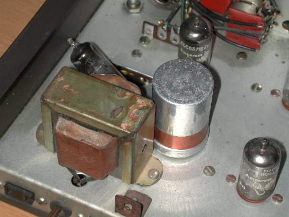
Here's my Eico HF-85 with its power supply filtering capacitor rebuilt using the above method. This repair was done in situ, though I don't recommend leaving the electrolytic in the chassis, since you have to solder to the terminals anyway.
Tim Reese