My "Darling" Variant
Although I’ve been dinking with tube audio stuff for a few years, this was my first attempt at a single-ended (SE) amp. Two events triggered this project; first, my friend Gary Kaufman somehow acquired a big batch of the 1626 tube. Second, I bought a Monarch SE 6BQ5 receiver which was in poorer shape than I realized at the time of purchase.
Regarding the 1626s, Gary has a talent for finding interesting tube-related stuff, and generously passes on the extras to his fellow tubeophiles without trying to make any profit. I traded him a bunch of 6J4WAs (same as 8532) that I found at the Rochester NH hamfest for several 1626s, thus I was half-way primed to do something with the 1626s.
If you aren’t familiar with the 1626, it’s an octal indirectly-heated triode (IHT) transmitting tube with an attractive ST (standard taper) shape. Originally designed for class-C service (i.e. pulses into a resonant circuit at a fixed frequency), and looking at its uneven plate curves, one would guess that the 1626 would make a lousy tube for audio. Enter Bob Danielak, who changed the reputation of the 1626 forever by building his "Darling" amps. Look at issue 15 of Sound Practices(SP) for a more complete description of the Darling’s history. The Darling circuit uses the 8532 as a driver tube, but I decided to do something a little different, as shown below.
Regarding the Monarch, I purchased the receiver for $50 through e-bay. Unfortunately, this receiver has a hole burnt in the multiplex board from a vaporized resistor. It could possibly be repaired, but I decided to lift the transformers for another project, with the intent that I could return them to the chassis should I want to restore the receiver.
The transformer set is quite nice — the power transformer (PT) has plenty of 6.3VAC capacity because of the large number of small-signal tubes in the receiver, an electrostatic shield, and a B+ voltage near what I needed for the 1626. The output transformers (OTs) are steel-encased, although they only have an 8 ohm secondary. I measured the impedance of the OTs at 4300 ohms… a single class A 6BQ5 biases at about 65mA, so I felt I could run two 1626s parallel SE (PSE, a "Double Darling") at 25mA each and stay within safe limits. I figured this would provide about 1.3W into an 8 ohm load, given the transformer impedance.
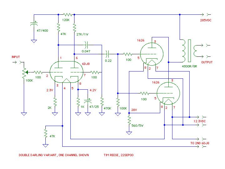
The Circuit ala TR
My circuit design changes the one-stage driver using a single 8532 to two stages ("amplifier" and "driver") using a 6DJ8. I have several ‘scope pulls in my junk box, and I wanted to try something a little more challenging than copying an existing design verbatim. Most of the rest of the changes result from adapting to parts on hand, and the PSE topology.
Here’s the diagram of one channel of the amp.
Let me point out a few details: The input also connects to ground, but I ran into the maximum devices limit in McCad-Lite, so I left that out. As shown here, the 3dB HF rolloff is about 120kHz, which surprised me. Likely the small size of the OTs maximizes the output bandwidth. Each grid has a 100 ohm carbon-comp resistor right at the grid pin, in an attempt to prevent any oscillation. The input stages are very conventional, using two cathode-bias RC-coupled stages. The driver stage (6DJ8 pins 6, 7, 8) has a cathode bypass capacitor which I originally calculated was needed for sufficient gain. Now that the circuit is in use, I find that I have too much gain, so it could probably be removed. I’m a little reluctant to remove it for fear of raising the output impedance of the driver and reducing the bandwidth… but I’ll try it one of these days. Hum across an 8 ohm load is about 2-3mV, with a tiny ringdown (less than 1mV, about 500uS) every 8.3mS, possibly from the diode switching (?).
Components are generics (a mix of plain metal film, metal oxide, carbon comp and wire wound resistors, some Xicon mylar coupling caps) or whatever scrounged-up or swap meet stuff I had on hand. Power supply electrolytics are from surplus, but I did use a quality electrolytic (Elna Cerafine) for the driver cathode bypass.
The rest of the operating points and the resulting component values were calculated using standard techniques (see Steve Bench’s web site for example, or the Radiotron Designer’s Handbook.)
The ground-reference resistor (47K, connected to the filament supply between the two 6DJ8s) is not duplicated on the other channel.
Here’s the power supply.
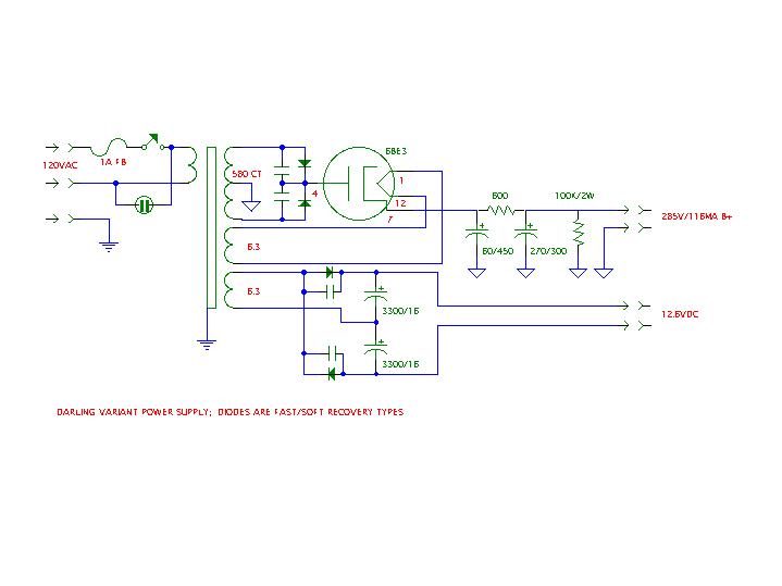
I started with a pair of chokes in the power supply (CLCLC) but eliminated them in favor of the CRC design. With cap input, the B+ voltage was too high, and the chokes weren’t large enough to be used for choke input, plus they took a lot of space under the chassis.
The rectifier diodes are GI soft/fast types (GI851 and GI856 from Digikey) bypassed with capacitors (0.47uf/100V stacked metal film and 0.01uf/1000V ceramic respectively) to further reduce the switching noise. After probing around with the ‘scope, I’d probably add some resistance in series with those caps to add some damping, or use John Camille’s snubber circuit (see back-issues of VALVE; also Jim Hagerman has a nice theoretical discussion of diode snubber design on his site), or use a vacuum tube rectifier. The 6BE3 is a damper diode which provides splendidly slow warmup. The voltage-doubler sits on its own board in the chassis, and adapts the 6.3V winding to the 12.6V needs of the 1626s.
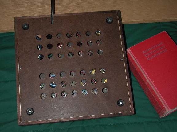
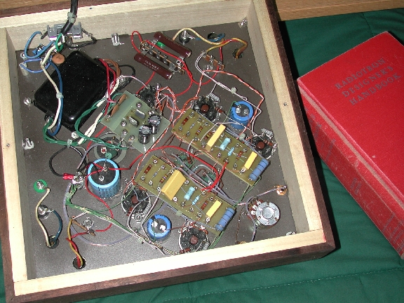
Pictures
Here are some low-res pictures I took with a friend's digital camera before the amp was finished — next time I can borrow the industrial-strength camera from work, I’ll take a bunch of new pictures and put some here.
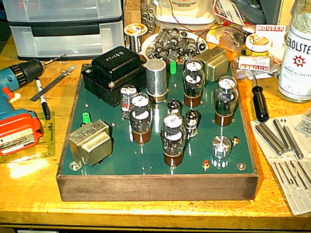


Notice that the two chokes seen in the underside views have been removed in the "finished" amp. The power supply capacitance has been changed around; The 60uF/450V capacitor is all three sections of the can capacitor in parallel. A single 270uF/300V capacitor replaces the large black capacitors mounted underneath. The single circuit board in the middle holds the voltage-doubler and the B+ rectifier. Each channel has its own turret board on which the resistors and coupling capacitors (yellow) are mounted. The blue electrolytic caps decouple the input stage B+. The filament wiring and some of the resistors have changed since these pictures.
Click on any of these pictures to show them full-size.
UPDATE 19NOV00: I removed the cathode bypass capacitor (47uF/25V) without any sonic penalty. Subjectively, it does sound better (although that may be the result of my increased attention) but certainly no worse. The gain is now more in line with what I had expected - when using my preamp (souped up EICO HF85 currently) I can set the volume knob on the Darling to 100% and have a usable range on the preamp from around 25% to 75%.
UPDATE 12NOV01: This amp still moves in and out of my system; It's had a couple of annoying failures in the meanwhile. First was an intermittent socket that would crackle and go open... maybe soldering and unsoldering too many times on a plastic socket. The socket was one of Handmade's green plastic 9-pins, and at $1 each I can't complain. The other problem was more serious - one of the diodes for the voltage doubler failed. The diodes were replaced with some 5A 60V Shottky types, and they run much cooler than the Si types, plus the filament voltage is closer to 12.6VDC nominal.
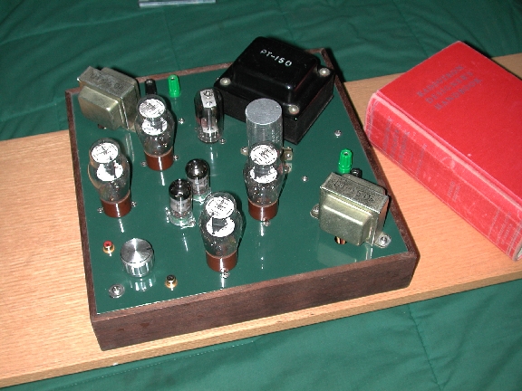
The Amperex 6DJ8s ('scope pulls) were replaced with Svetlana 6N1Ps, with a definite improvement in sound. The 6N1Ps beat all my 6DJ8s, including various Amperexes, Mullards and ECG Sylyania JAN 7308s. Here are a few newer pictures.
Listening Impressions
I’m amazed at how good this amp sounds, within its limits. Certainly, you can make the sound harshen and harden by trying to go too loud, but my Ariels (about 92 dB/W) can be driven loud enough that I worry about disturbing the neighbors in my small apartment. Sonically, there’s nice detail with perhaps a bit of a low bass hump, which actually sounds good on most material. I’m surprised at the nuances and complexities that I’m hearing in very familiar music… perhaps that’s a bit of the SE "magic."