Notes for Brook 12A Clone
1) Power Supply
25APR00
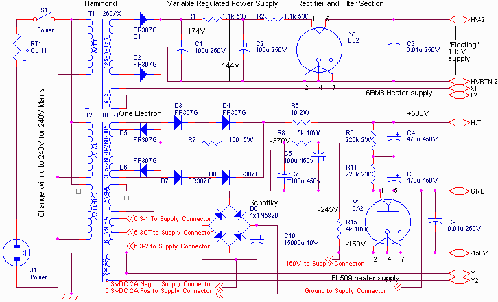
The power supply is a series-regulated supply from Steve Bench's web site. The schematic for the power supply is

where I've made the following substitutions and modifications:
• 6LX6 has been subbed for the EL509 because I had it on hand.
• The 0A2 and 0A3 are replaced by the 0D3/VR150 and 0C3/VR105 respectively.
• BFT-1 has been replaced with a milspec transformer with separate 770VCT/280mA and 750VCT/175mA taps. This may be a problem if the 0D3 is unplugged or goes open since the caps across the -150V supply are rated at 450VDC. Fine for 260-0-260 (1.414*260 = 368) but a problem with 350-0-350 (1.414*375 = 530V). Perhaps I will add a bleeder to keep the unloaded voltage below 450V. Either that or replace the e-caps with a higher rating; but I'd need 4 x 200uF/300V minimum. This seems like the better option.
• The 105V floating supply is powered by a 25VA Magnetek isolation transformer from Mouser.
• 2 6CG3 damper diodes have been added to the ground return, with filament power from the milspec power transformer. This may be superfluous given the warmup characteristics of the 6LX6.
Filament supplys come from a separate milspec filament transformer, supplying both tubes (6LX6 and 6BM8) plus a 6A 6.3VAC CT external connection. Two 5VAC 6A external connections are provided from the power transformer.
Most of the work is done; I'm waiting for higher quality wire from Tony at Handmade since I'm tired of working with PCV wire that melts. Then I'll do some testing of the raw part of the supply for proper operation, including the bypass resistor to prevent overvoltage on the 150V supply. Then the basic supply will be tested; the diagram for the regulation part follows.

I've added a 20uF oil cap to the output which will be optionally connected across the output.
After testing the basic supply, the feed-forward modification will be added. Following testing of this addition, the supply will be complete.

TO DO: Get wire.
Finish wiring of passive PS stage.
Test passive stage.
Test for value and add bypass resistor.
Wire pass tube and error amplifier.
Test PS w/o feed forward.
Wire feed forward circuit.
Test PS with feed forward.
27APR00
I've decided to replace C5 and C7 on the -150V supply in order to avoid overvoltage at startup or when the 0D3 is pulled. The higher supply voltage requires a larger dropping resistance too: (367 - 150V) / 9100 R = 0.24mA; instead I'll have (530 - 150) / 9100 = 42mA, within the range of the 0D3 but I'm going to change R15 to 10K instead (added to latest Mouser order).
The capacitors will come from All Electronics Supply, 4 ea of the 270uF/300V with 2 in series and resistor bypassed at each position.
The bottom plate and wire for the PS arrived yesterday from Tony at Handmade. More wiring to commence real soon.
28APR00
Attached the bottom plate and feet yesterday. Need to remember to get an ST 0D3.
2) Amplifier
25APR00
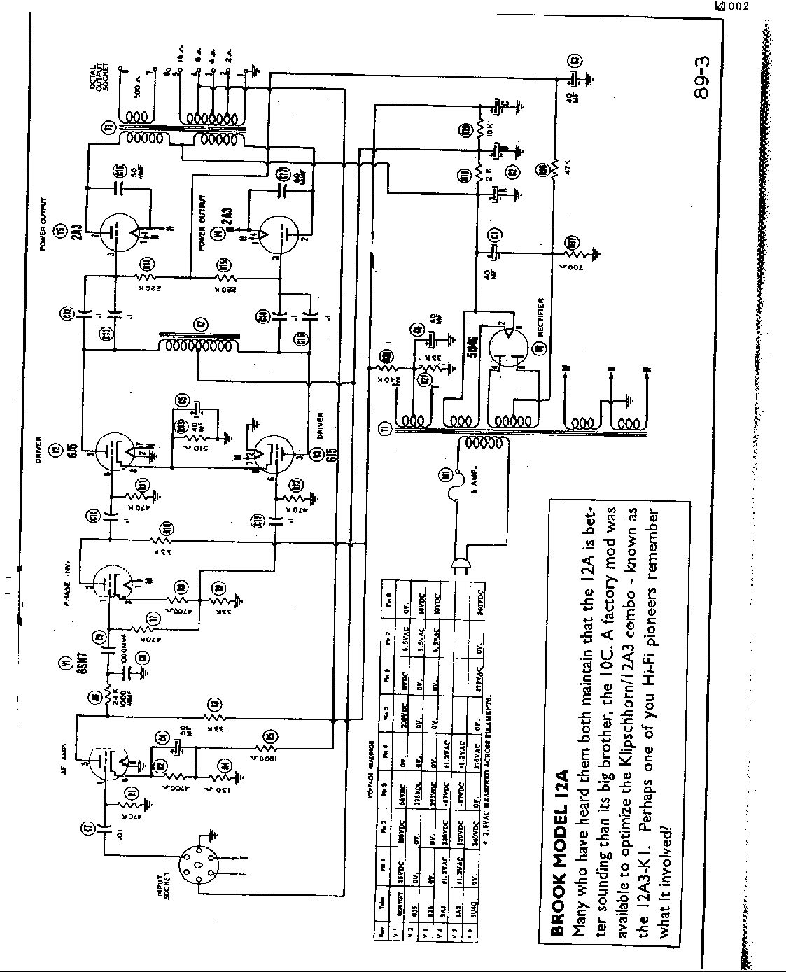
The circuit diagram:

The amplifier has been languishing on its breadboard for the past year, awaiting a power supply. The amp is essentially a Brook 12A with the following changes:
• 6A3s are substituted for 2A3s, since they were available and should be fine running AC filaments in a push-pull amp.
• I have a pair of Mike's CT audio chokes which may be less tolerant of unbalaced DC than they should be, or may have a lower inductance than they should... I need to talk to Mike to resolve this. As I recall they are gapped and shouldn't be, or vice versa. If thay have a gap, they are more tolerant of unbalanced DC but have lower inductance. This is what I remember Mike telling me, but it's contrary to what I read from Paul Joppa on the Joe List. Quothe Paul:
0mA 61H
1mA 53H
2mA 44H
3mA 37H
4mA 32.5H
5mA 29H
This is end-to-end inductance. By my rule of thumb (250 ohms per henry) that with less than 2mA unbalance, the inductance is just (barely) enough to use with a pair of 6J5's as done by Brook. I'd rather use something with 5k or less plate resistance. More than 2mA unbalance is too much, IMHO.
•
I got a bargain on some VT-94s (JAN 6J5Gs) that look cool, but they may have a bit of a high plate resistance (Rp) for the CT choke that I'm using.• I've substituted 2 6.3VAC CT @ 3A filament transformers for the 6A3 filaments.
• The PS above has a regulated negative bias supply, so I'm using true fixed bias instead of the faux fixed bias on the original schematic.
• If the unbalanced DC is a problem in the CT choke, I'm adding a current mirror to the cathode leg of the driver circuit.
I could substitute Electroprint's CT audio choke for Mike's choke and Mike's choke on another project. If I use a lower Rp driver tube, the problem with the lower inductance will be relieved. This should also relieve the need for the current mirror.
The original amp used a 700 ohm resistor in the ground leg of the amplifier to reference the 5U4G 67V below ground by making the resistor half of a voltage divider with the 2A3 plate resistance. Without that resistor, the plate voltage should be 330V and the filament CT goes to ground. The quiescent current of each 2A3/6A3 is 45mA with -67V on the grid.
Spoke to Jack Elliano about Mike's chokes, and he claimed that they may be on the slightly low side of acceptable for the 6J5 but that I should use them. He claimed that a reactor (as he called it) is not affected by the plate resistance of the driver tube, but then he claimed that a lower Rp tube would be better. Perhaps my conversing with him was not clear - looks like I should go ahead and use the chokes though.
Chassis Design:
The chassis will incorporate my new FR-4/ aluminum "sandwich" design which promises to be rigid, easy-to-build and easy-to-modify.
The only screws that protrude through to the top plate secure the spacers at the corners and capture any additional spacers between the top plate and the FR-4. These can be placed at corners of transformers and strategically across the top plate to ensure chassis rigidity. Spacers are nylon plain spacers for #8 screws, Mouser 561-K8.625. Screws and nuts can be purchased at the local home center or from Small Parts Inc.

Usually I'd use eyelets to secure PC mount sockets to the subchassis, but I have plenty of octal sockets and the needed 4-pin sockets do not come in PC mount, so a clearance hole is drilled in the FR-4 (1.125" diam) and the sockets are mounted to the subchassis conventionally. Component mounting relies on rows of turrets mounted to the FR-4 subchassis. A wood surround will be constructed to enclose the edges and hide the subchassis.
TO DO:
Layout the chassis using components and templates.
Design current mirror and fixed bias divider.
Make an inventory of the components needed and order
what's missing.
Layout and drill the top plate.
Lay out, drill and install turrets in the subchassis.
Install components on subchassis.
Wire subchassis.
Put the subhcassis and top plate together with components.
Finish wiring.
Build wood surround.
Test.
28APR00
Added new chassis design drawing (arghh). After measuring the sockets, nylon spacers should be 0.5" OAL (Mouser 561-K8.50).
Some items need to be added to the parts list, including the power supply connectors, current mirror transistors and hum-balancing pots.
AF = 6SN7 audio frequency amp, PI= 6SN7 phjase inverter, D = 6J5 driver, FD = fixed bias divider
Parts list per channel, original schematic
R1 470K AF grid pulldown ˆ Xicon C/C
R2 4700 AF cathode, bypass (order)
R3 33K AF plate (order)
R4 130 AF cathode (order)
R5 1K AF feedback (order)
R6 24K AF filter (order)
R7 470K PI grid pulldown ˆ Xicon C/C
R8 4700 PI cathode, top (order)
R9 33K PI cathode, bottom (order)
R10 33K PI plate (order)
R11,R12 470K D grid pulldown ˆ Xicon C/C
R13 510 D cathode (order)
R14, R15 see below
R16 deleted
R17 deleted
R18 2.4K PS dropping ˆ surplus MF
R19 5K PS dropping ˆ surplus MF
C1 deleted, part of power supply
C2 3 x 100uF 450V ˆ Panasonic TSHA
C3 40u/450V FD decouple ˆ Nichicon
C4 47u/100V AF cathode decouple ˆ Nichicon Muse
C5 47u/100V D cathode decouple ˆ Nichicon Muse
C7 deleted
C8 1n/500V AF filter (order)
C9 100n/400V PI coupling ˆ Sequa
C10,C11 100n/400V D coupling ˆ Sequa
C12,13 200n/400V OP coupling ˆ Sequa
C14,15 200n/400V OP coupling ˆ Sequa
C17,C18 50p/500V OP filter ˆ silver mica
We need --67 volts at the grid with a 330V plate voltage. The grid of the original drawing is 220K to ground, so retain that loading for the grid. 150V input, the top and bottom halves of the divider should be 220K total load. Top:Bottom 0.553:0.447
(1/0.553R + 1/0.447R) = 1/220K, R = 890K : 492K and 397K
Parts per channel, new fixed bias divider
R14a,R15a 499K FD top
R14b,R15b 402K FD bottom